-40%
RF VHF / UHF Power Amplifier Amplifier RF Power Amplifier For Mitsubishi RA
$ 9.49
- Description
- Size Guide
Description
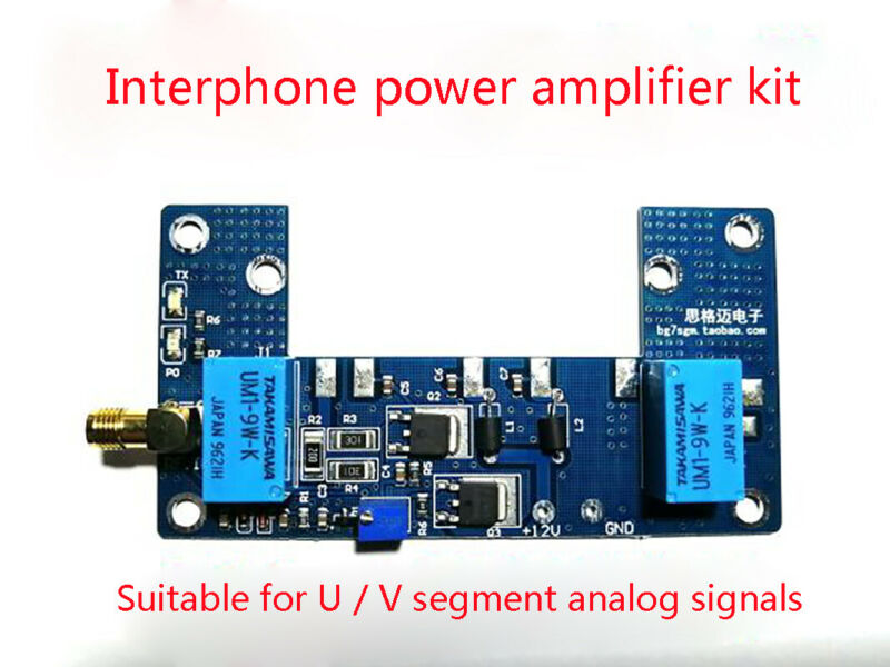
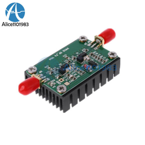
The PCB board is the peripheral circuit of the power module. It must work with Mitsubishi's RA, M series, and Toshiba's S series modules to work properly. This board is mainly developed for 1-5W handheld walkie-talkies, with automatic transceiver conversion circuit. Increase the transmission power of the walkie-talkie so that the handheld walkie-talkie has the power of the car station, so that the communication is farther and the voice is clearer.Parameters:
Input power: 1-5W
Output power: 10-80W (depending on the module)
Input voltage: DC 12-13.8V
Working frequency: 136-170 400-470 (depending on the module)
Insertion loss: -1.5DB
Standing wave ratio: ≦ 1.5
Appearance size: 94 * 50 * 1.6MM
Debugging:
Before debugging RA series modules, all pins must be removed from the PCB board, and all pins can only be soldered after the voltage is adjusted.
The second pin (VGG) from the left of the RA module has a working voltage of 2.3-3.3V (the higher the voltage, the greater the output power). Before debugging, connect the intercom to the PCB board, and then prepare the multimeter, turn the multimeter to DC voltage, then connect the red test lead to the second pin (VGG) of the module on the PCB board, the black lead to the negative pole, then press the radio button of the intercom, then adjust the blue potentiometer on the board Small) can read the voltage value on the multimeter.
The working voltage of the M or S series module is 10-14V, you can directly install the module on the PCB board and adjust it to 10-12V.
Note:
there is a Plug-resistor no welded, if you use M or S series amplifier module ,you should remove the Plug-resistor R6. if you RA series amplifier module, you shoud seld the plug resistor.
Packing List:
1pc x Radio Amplifier Board
